When working on a Revit project, one of the very first things to set up is the Project Base Point and how it relates to your project levels.
There are two types of elevations that we need to keep in mind: architectural levels and surveyor’s levels. Architectural levels typically start at 1,000,000 mm (or 100′-0″). These are virtual elevations widely used in architectural projects because they are easy to read and help avoid negative level values for basement floors.
In Revit, there are two key controls that determine how elevations are displayed in your project: the Project Base Point and the Survey Point. By adjusting these two elements correctly, you can ensure that your project shows accurate and consistent elevations.
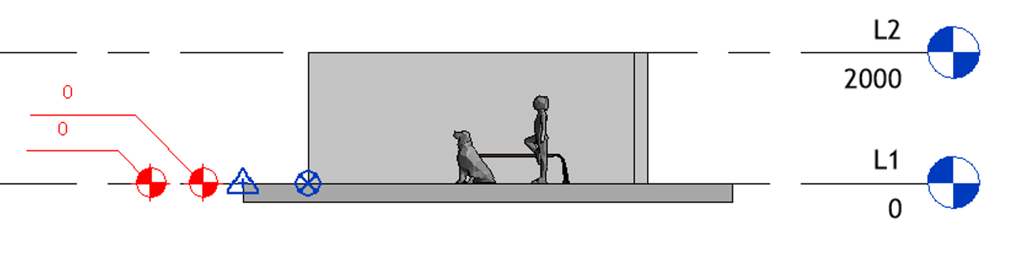
There is a simple Revit model shown on the first image. The Survey Point has an elevation of 0, and Level 1 is also set to 0. The spot elevations for both the Project Base Point and the Survey Point are 0.
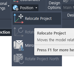
First, move the Survey Point to its real-world location or manually enter its elevation. Then, use Relocate Project from the Project Location menu. By doing this, you set the Survey Point to the real-world coordinates and physically move the project to align with that Survey Point.
The next step is to move the Project Base Point. The Project Base Point is always placed below the Survey Point so that project level elevations display as positive values. Select the Project Base Point, then move it downward and enter 1,000,000.
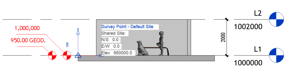
Finally, as you can see, the project elevations display 1,000,000, while the spot elevations for the Survey Point show the correct real-world geodetic elevations.
This setup is not very difficult, but if you haven’t done it before, it can take some time to achieve the best display of both geodetic and project elevations in Revit.